

2025-05-09
3 kV voltage multiplier
Voltage multipliers are key elements in electronics that allow you to obtain high DC voltage from an AC source without using bulky transformers. Their simplicity, compactness and efficiency make them indispensable in various fields, from household appliances to scientific research.
In this note, we will consider one of the most popular multiplier circuits with some additions. Here we will describe the principle of its operation, provide a circuit and a printed circuit board of a 12-link multiplier that allows you to increase the mains voltage from 220 V to 3 kV, as well as a calculator for calculating such a circuit with other input parameters.
Why do you need voltage multipliers
Many applications require high voltage at relatively low current. Voltage multipliers allow you to achieve this without using heavy and expensive transformers. They are widely used in:
- X-ray machines;
- electrostatic systems;
- particle accelerators;
- laser installations;
- copiers and printers;
- TVs and oscilloscopes;
- avalanche mode circuits (example).
Main Types of Multipliers
There are several types of voltage multipliers, each with its own characteristics and applications:
- Voltage doubler: the simplest circuit that doubles the input voltage. By adding additional stages, the device receives a proportional increase in output voltage.
- A variation of the previous circuit can be a symmetrical version, the advantage of which is twice the output voltage, and the disadvantage is the lack of a common bus at the input and output.
- Cockcroft-Walton generator: a cascade circuit that allows you to get very high voltages. Widely used in particle accelerators and other scientific installations.
General operating principle
The basis of the voltage multiplier is diodes and capacitors connected in a certain sequence. During the positive half-period of alternating current, the capacitors are charged through the diodes. During the negative half-period, the charge is redistributed, and the output voltage increases. Each additional stage (link) of the multiplier adds a certain value to the output voltage. Thus, the total output voltage Un becomes approximately equal to the amplitude value of the input U, multiplied by the number of stages n (Fig. 1).
 Fig. 1. Diagram of cascade voltage multiplication from n links |
If reverse polarity is required at the device output, all diodes are simply rotated 180 degrees.
12-link multiplier for 3 kV
Some studies require a constant voltage of about 3 kilovolts. It can be obtained directly from a 220 V network using a 12-link multiplier circuit (Fig. 2). A distinctive feature here are resistors R1-R12, located parallel to capacitors C1-C12. They are necessary for the safe operation of this device. About 10 seconds after disconnecting from the network, a safe voltage remains at the circuit output.
 Fig. 2. Schematic diagram of a cascade voltage multiplier of 12 links for 3 kV |
Attention. There is high voltage at the input and output of this circuit. Work with the device requires strict adherence to all electrical safety rules! Careless handling may result in injury or damage to the equipment.
The device is connected to a 220 volt network, and the GND contact must be connected to the neutral (N). Then, at the output, the corresponding GND contact will bealso have a relatively safe neutral potential. The best solution would be to connect the circuit to a LATR transformer, where output voltage regulation is possible. In this case, you get a high-voltage source that can be regulated in the range from zero to 3000 V.
You can find an example of this scheme here.
Element base
All capacitors C1-C12, resistors R1-R12 and diodes D1-D12 are the same. Capacitors can be taken of the brand CBB22 for 630 volts or more. With these circuit parameters, they should have a capacity of 3.3 μF. To increase the output current, you can simply increase the capacitance of the capacitor. However, in this case, you will have to slightly modify the printed circuit board to accommodate larger elements.
Any diodes with a voltage of 1000 V and a current of 1 A are suitable for this circuit. Diodes of the FR207 brand have proven themselves to be good. It is better to choose SMD resistors of the 2512 size.
Printed circuit board
The above element base is used in the following printed circuit board of a multiplier measuring 201*46 mm (Multiplier). Additionally, a kit for making a voltage divider from 3 kV to 300 V (Divider) is available, which is necessary for measuring the output voltage of the multiplier using a regular tester.
Production version: PCB (open)
The production option provides a set of documentation for manufacturing a printed circuit board in production:
GERBER file for PCB, BOM file of the specification of components and a schematic diagram showing the values of the elements.
All this allows you to immediately order a PCB, for example, here, and then quickly assemble it.
 | 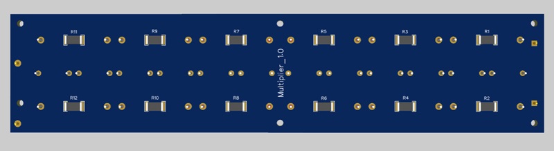 |  |
A small addition. Experiments have shown that the optimal value for resistors R1-R12 should be between 2.7 and 3 MOhm.
Device Enclosure
You can make your own device in any suitable enclosure. The author created it using a 3D printer, adding a high-voltage voltmeter and milliammeter to the circuit for better visualization of its operation.
 Fig. 3. Device Appearance |  Fig. 4. Device Interior |
During installation, a special high-voltage wire can be used. However, since the voltage in the circuit does not exceed 3 kV, all wires can be placed in double-walled tubing.
Production version: 3D body (open)
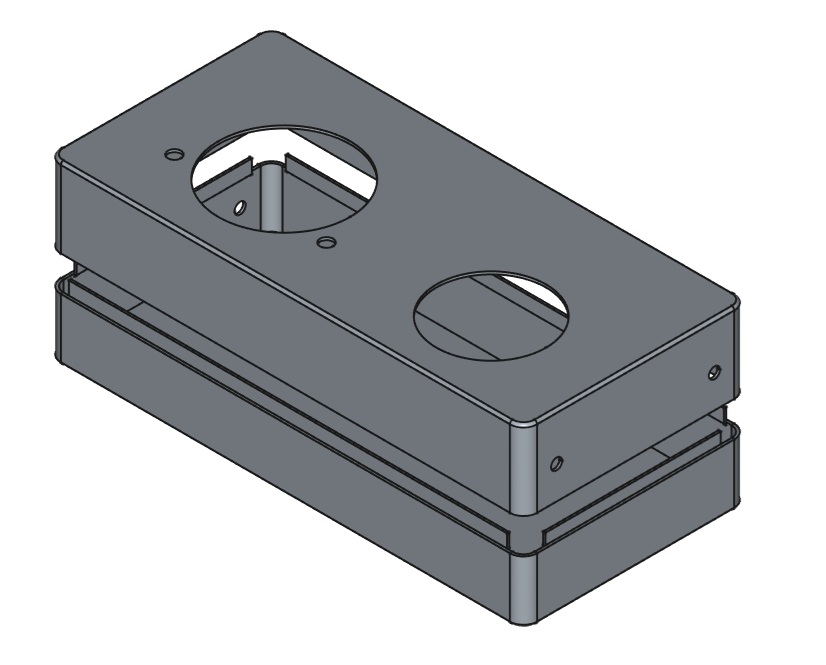
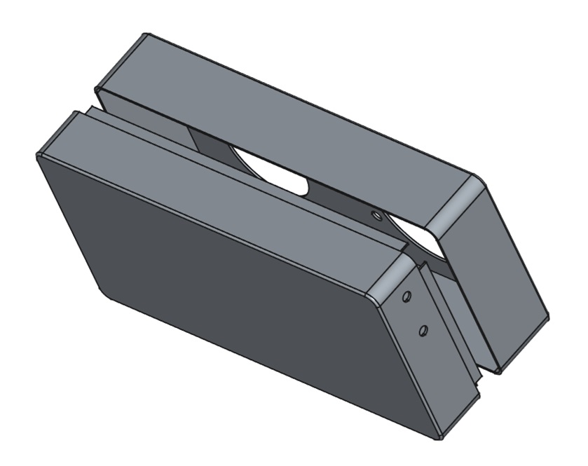
Placing such a device in an enclosure protects the board from dust and accidental contamination by other materials, which can sometimes be critical for high-voltage components.
Calculator
Below is an online calculator for calculating the parameters of a voltage multiplier in a 50 Hz or 60 Hz network. By default, the parameters of a 12-link multiplier are selected, the circuit and printed circuit board of which are provided in this work.
Output voltage, V:
Output voltage rise time, sec:
Output voltage ripple amplitude, B:
Maximum current through the diode, A:
Voltage on the diode, V:
Note to the calculator. The input voltage here is assumed to be effective. The output current is the current through the load connected to the multiplier output.It affects the output voltage, so it must be taken into account when calculating. The range of values of this current can be increased by increasing the capacitance of the capacitors. Such a change will also lead to a decrease in output ripple.
The maximum current through the diodes depends on the output current, as well as on the capacitance of the capacitors. Thus, the diode must be selected for this current, and for the doubled amplitude value of the input voltage, which is also given in the output data of the calculator. The same voltage value can be used to select the maximum voltage of the capacitor.
The rise time of the output voltage is the time during which 95% of the declared voltage will be reached at the output of the multiplier. The fact is that the chain of capacitors is charged sequentially and this process takes time.
The efficiency of the multiplier begins to decrease when the number of links exceeds twelve.
Safety Warning
⚠️ This article describes a device for multiplying line voltage to 3 kV (3000 V). Working with line voltage equipment, and especially high-voltage equipment, is mortally dangerous and can result in electric shock, severe burns, fire, insulation breakdown, and component failure.
Reproduction of this design is permitted only by specialists experienced in working with high voltages, in strict compliance with electrical safety regulations and the use of suitable insulating materials and measuring equipment.
The author is not responsible for injuries, damage, or other consequences associated with attempts to independently assemble, configure, or operate the device.
Reproduction of this design is permitted only by specialists experienced in working with high voltages, in strict compliance with electrical safety regulations and the use of suitable insulating materials and measuring equipment.
The author is not responsible for injuries, damage, or other consequences associated with attempts to independently assemble, configure, or operate the device.