

2024-09-22
Toroidal coil and short pulses
According to classical concepts, the magnetic field is inside the toroidal coil and should not go outside.
The magnetic flux, however, passes through the cross-section of the torus.
But everything changes when a sufficiently short pulse is applied to such a toroidal coil (TC).
Then the magnetic field begins to go outside, and its amplitude depends on the location of the measuring head on the coil.

Fig. 1. Experimental scheme and graphs of magnetic field strength along different surfaces of the torus T1
|
The scheme of our experiment is shown in Figure 1.
Two turns of thick wire are wound on a toroid made of ferromagnetic material T1 and connected to the pulse generator GG1.
In this case, the author used the following generator,
but any other one that gives good values of the pulse front and fall time can be used.
The total power consumption of the generator was 2-2.5 W with a toroid size of 80*50*25 mm.
Within certain limits, the effect proposed here did not depend on this power.
The limitations concerned the maximum voltage on the generator output transistor.

The toroid is made of nanocrystalline,
with a relative magnetic permeability of approximately 130 thousand units.
Pulses were applied to two turns wound on it, the oscillogram of which is shown in Figure 2.
The most important moment that will interest us is in the first 250 ns of the pulse, when it sharply increases and decreases (Fig. 3).
It is at this time that the effect of the magnetic field outside the TC that we need appears.
The measuring device (measuring head) is a turn of copper wire, 10 mm in diameter, connected to an oscilloscope.
The experimenter brought it to three faces of the torus with the generator turned on: P1 is the upper face of the TC, P2 is the outer face of the TC, P3 is the inner face of the TC (Fig. 1).
Depending on the position of the measuring head relative to the two turns of the winding, the amplitude of the signal on the oscilloscope changed.
The highest amplitude was observed near two turns (Fig. 4), and the lowest - opposite them.
The full dependence of the signal amplitude on the observation angle is shown in Fig. 1 (right graph).

Fig. 2. Voltage pulses on two turns of the TC | 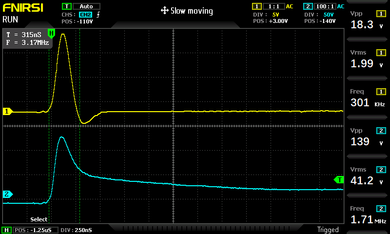 Fig.3. Voltage pulse on two turns of the TC (blue beam), and current through them (yellow beam)
|
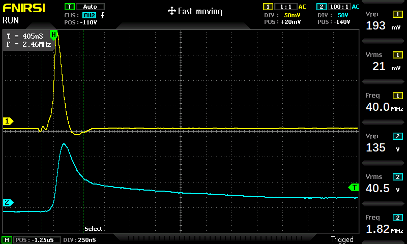
Fig. 4. Voltage pulse on the TC (blue beam) and pulse in the measuring coil (yellow beam)
|
It is necessary to pay attention to the duration and shape of the signal on the measuring head (Fig. 4):
it does not correspond to either the shape of the current signal or the shape of the voltage signal on the two turns of the TC (Fig. 3),
and is a time derivative of them.
From this we can derive the following pattern:
\[ U_2 \sim {d U_1 \over d t} \tag{1}\]
Here \(U_1\) is the amplitude on two turns (at the output of the generator GG1), \(U_2\) is the amplitude on the measuring head, and \(t\) is time.
That is, the faster the voltage change on the transmitting winding of the TC, the greater the amplitude of the pulse on the measuring head will be.
Usually, as in our toroid, the limitation on the pulse duration is caused by the material of the ferromagnet and its ability to undergo magnetization reversal.
This means that the manifestation of the effect depends more on the properties of the TC material rather than on the generator itself.
For comparison, it should be said that in a classic transformer, the pattern (1) would look like this:
\[ U_2 \sim U_1 \tag{2}\]
That is, the voltage in the secondary winding would be proportional to the voltage in the primary.
Ator believes that the appearance of a magnetic field outside the TC cannot be caused by Foucault currents, since they are formed along the plane of the sheets of ferromagnetic material [1],
and therefore the direction of the magnetic lines of force should be strictly perpendicular and appear only in the P2-P3 plane,
since the toroid is wound at the factory in turns of thin sheets of nanocrystalline material.
In addition, Foucault currents should evenly distribute the output of the magnetic fieldand the limits of the TC along its entire circumference.
In our experiment, the magnetic field extending beyond the TC is directed in different directions, and the strongest one is in the P1 plane.
The distribution of this field along the circumference is clearly uneven (Fig. 1, right graph).
Such a manifestation is characteristic only of the second magnetic field.
Electric field around the toroid
Also, the electric field strength was measured along different surfaces of the toroid.
Unlike the magnetic field, the electric field along the surface remained virtually unchanged: \(E(\alpha) = const\),
but it depended on the surface itself approximately as follows: P3 - 30 mV, P1 - 55 mV, P2 - 100 mV.
That is, inside the torus, the electric field strength was three to four times less than on its surface.
Such a field distribution cannot be explained only by interference from the exciting winding, although it does occur.
Materials used
- Wikipedia. Eddy currents.