

2016-12-28
Study of coil inductance 1/4 wavelength
Recently in the network are discussed such questions as: can the LC resonance to work separately from the mode of the standing wave and how these two inherently different resonance influence each other. In this paper, we propose more studies, some of which will help to answer them. Here we will explore the single-layer coil inductance and the LC resonance, with the length of the coil is going to fit 1/4 of the full wave. This incorporation of coil is used, for example, in the Tesla transformer.
The experimental setup is depicted in figure 1.1. Inductor L1 is placed on the investigated coil L2 located in its lower part. The inductor is fed a sinusoidal signal source VS1. In one mode, the lower end L2 may be connected to ground through the switch SA1. The findings of this coil is connected to the stand ST, which will be described below. The distribution of the electric field |E| is controlled by the indicators described here. Clearly this distribution is presented in the following figures: 1.2 — without a connection to ground, and 1.3 — connecting.
Fig. 1. Schematic diagram of the experiment. The distribution of electric field intensity in the coils in different modes
Stand ST discretely allows you to change the capacity of the external capacitor connected to L2 and to indicate a maximum of |E| in the search of the resonance frequency. Its schematic diagram is shown in figure 2. There is a photo of his constructive realization. All the capacitors C1-C5 have the same capacitance — 8 pF, depending on the switches SA3-SA5, discretely change the capacity on his findings. Capacity of the stand (cables and switches) turned out to be about 4 pF. Therefore, stand by the conclusions of the XS1-XS2 can give such capacitance values are 0 (disconnected from the stand L2), 4, 8, 12, 16, 20, 24, 28, 32 pF.
In addition, the stand allows you to find the maximum tension at the top point of the coil L2. Indication of the maximum observed at maximum brightness of the led HL1, while switches SA1 and SA2 are open! This effect is possible thanks to a fork Avramenko collected on the diodes VD1, VD2. Additionally, the field distribution and resonance is controlled by the maximum of these indicators. By the way, the stand is quite versatile and can be used for studies of the half-wave resonance, then SA1 and SA2 should be in the closed position.
In case of recurrence of this, consider the following guidelines. Use only details: VD1, VD2 — UF4007, VD3, VD4 diodes — 1N4148. Capacitors C1-C5 is a high frequency, preferably tubular, like the CTC. Led HL1 must be from the SuperBright.
 |  |
Fig. 2. Schematic diagram and appearance of the stand | |
The results of the research
To do this, put on the test coil L2 inductor, podklyuchaem stand and write the data into the table. The author has applied various types of coils at different frequencies from 100 kHz to 10 MHz. Data on some of these are listed below. Left — photo of the investigated coil and under it is its characteristics. Right — of data under different modes and the switches of the stand. Indicate here are: CI — the self capacitance of the coil, pF; CGND — capacity of land (0 — land is not connected); CADD the capacity of the stand (0 — not connected); fM is the measured resonant frequency, MHz; fCL — the calculated resonant frequency, MHz; δ — error, in percent.
The studies were carried out on the basis of several assumptions. First — that at frequencies from 100 kHz to 10 MHz the resonance is calculated according to the formula of Thompson, but with some additions. The second ground connection to the bottom end of L2 changes its resonance frequency, and the calculation proizvodnja as well, but the formula is added to the capacity of the earth. The General formula to calculate this:
\[f_{CL} = {1 \over 2\pi\sqrt{L\,(C_{I} + C_{GND} + C_{ADD})}} \tag{1}\]
where: \(L\) is the inductance of the coil L2. Producing real measurements of fM and comparing it with the calculated fCL, we obtain the error δ by which we will judge the correctness of our assumptions.
1

Inductance, mH — 0.66
The number of turns — 248
Wire length, m — 39.3
Length of winding, mm — 205
The reel diameter, mm — 50
Wire diameter, mm 0.6
| CI | CGND | CADD | fM | fCL | δ |
| 2.9 | 0 | 0 | 3.52 | 3.64 | 3.3 |
| 4 | 2.37 | 2.36 | 0.5 | ||
| 8 | 1.93 | 1.88 | 2.8 | ||
| 12 | 1.65 | 1.60 | 2.7 | ||
| 20 | 1.32 | 1.29 | 1.9 | ||
| 32 | 1.08 | 1.05 | 2.9 | ||
| 2.9 | 1.7 | 0 | 2.85 | 2.89 | 1.4 |
| 4 | 2.06 | 2.11 | 2.5 | ||
| 8 | 1.76 | 1.75 | 0.8 | ||
| 12 | 1.51 | 1.52 | 0.7 | ||
| 20 | 1.26 | 1.25 | 0.9 | ||
| 32 | 1.04 | 1.02 | 1.5 |
2

Inductance, mH — 12.5
The number of turns — 434
Wire length, m — 273
Length of winding, mm — 510
The reel diameter, mm — 200
Conductor diameter, mm 1.1
| CI | CGND | CADD | fM | fCL | δ |
| 8.9 | 0 | 0 | 0.493 | 0.48 | 3.2 |
| 4 | 0.389 | 0.40 | 1.9 | ||
| 8 | 0.345 | 0.35 | 0.4 | ||
| 12 | 0.31 | 0.31 | 0.4 | ||
| 20 | 0.26 | 0.26 | 1.8 | ||
| 32 | 0.22 | 0.22 | 1.2 | ||
| 52 | 0.18 | 0.18 | 1.3 | ||
| 8.9 | 3.8 | 0 | 0.41 | 0.40 | 2.6 |
| 4 | 0.34 | 0.35 | 2.5 | ||
| 8 | 0.304 | 0.31 | 2.9 | ||
| 12 | 0.28 | 0.29 | 2.3 | ||
| 20 | 0.243 | 0.25 | 2.4 | ||
| 32 | 0.209 | 0.21 | 1.9 | ||
| 52 | 0.175 | 0.18 | 1.1 | ||
| 94 | 0.135 | 0.14 | 2.1 |
3

Inductance, mH — 5.2
The number of turns — 993
Wire length, m — 157.5
Length of winding, mm — 440
The reel diameter, mm — 50
The diameter of wire, mm 0.4
| CI | CGND | CADD | fM | fCL | δ |
| 4 | 0 | 0 | 1.13 | 1.10 | 2.3 |
| 4 | 0.78 | 0.78 | -0 | ||
| 8 | 0.64 | 0.64 | 0.4 | ||
| 12 | 0.55 | 0.55 | 0.3 | ||
| 20 | 0.45 | 0.45 | 0.1 | ||
| 32 | 0.367 | 0.37 | 0.2 | ||
| 4 | 2.5 | 0 | 0.89 | 0.87 | 2.7 |
| 4 | 0.67 | 0.68 | 1.7 | ||
| 8 | 0.571 | 0.58 | 1.5 | ||
| 12 | 0.502 | 0.51 | 2.2 | ||
| 20 | 0.417 | 0.43 | 2.8 | ||
| 32 | 0.35 | 0.36 | 1.6 |
4
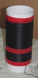
Inductance, mH — 0.63
The number of turns — 119
Wire length, m — 37.8
Length of winding, mm — 175
The reel diameter, mm — 101
Wire diameter, mm 1.2
| CI | CGND | CADD | fM | fCL | δ |
| 4.7 | 0 | 0 | 2.82 | 2.92 | 3.7 |
| 4 | 2.21 | 2.15 | 2.7 | ||
| 8 | 1.84 | 1.78 | 3.3 | ||
| 12 | 1.59 | 1.55 | 2.4 | ||
| 20 | 1.29 | 1.28 | 1.1 | ||
| 32 | 1.07 | 1.05 | 2.2 | ||
| 4.7 | 1.9 | 0 | 2.41 | 2.47 | 2.4 |
| 4 | 1.93 | 1.95 | 0.9 | ||
| 8 | 1.67 | 1.66 | 0.6 | ||
| 12 | 1.47 | 1.47 | -0 | ||
| 20 | 1.22 | 1.23 | 0.8 | ||
| 32 | 1.025 | 1.02 | 0.4 |
Insights
1. The calculation of the LC resonance in the case of 1/4 wavelength is made according to the formula of Thompson (1.1) with sufficient accuracy. As can be seen from the tables, the error does not exceed 4%, which is acceptable given that completely avoid the interference of surrounding and secluded containers, which can distort the results, will not succeed.
2. The connected capacity of the earth is taken into account in equation (1.1) by simple summation with its own capacity of the coil and the capacity of the stand. Therefore, the capacity of the earth you can search by the following formula:
\[C_{GND} = {1 \over (2\pi)^2L} \left(\frac{1}{f_1^2} - \frac{1}{f_2^2}\right) \tag{2}\]
where: \(L\) is the inductance of the coil L2, \(f_1\) is the measured resonant frequency with L2 connected to ground, \(f_2\) is the measured resonance frequency of L2 without ground. Thus, in order to find the capacity of the land in the area and for a given coil, it is enough to know its inductance and produce just the two measure.
3. For some designs, coil calculations show superluminal values for the speed of propagation of the wave. To explain this, only inter-turn capacitance and the magnetic coupling, which can be quite different for different values of the winding pitch, it is impossible. It is assumed that this is an indirect sign of the presence of longitudinal electromagnetic waves.
4. Tesla transformer cannot be considered only as a special case of long lines, as such, may not be exceeded the limit of light speed. In addition, the patterns of change in the parameters of such a transformer does not correspond to the mathematical models of the long lines.
The results of these studies were designed calculator, which made adjustments to the calculation of inductance, self-capacitance and capacitance of grounding. In addition to the normal parameters it can calculate the ratio of the speed of propagation of waves in the coil and the capacity of the ground for the area.
Addendum as of 08/16/2022
As a result of additional research, empirically, it was possible to find out a rather simple dependence of the ground capacitance on the parameters of the Tesla transformer:
\[ C_{GND} = \varepsilon_0 H^{0.75 }D^{0.25} = \varepsilon_0 D\, k^{0.75} \tag{3}\]
where: \(\varepsilon_0\) - absolute dielectric constant, \(H\) - winding length of the transformer coil, \(D\) - coil diameter, \(k = H/ D\) - form factor.
It is assumed here that the grounding of the Tesla transformer corresponds to its dimensions, and all formulas in this paper are presented in the SI system of units.