

2025-01-26
Light as scalar waves
"In reality, everything is not as it really is!" Karl Kraus, German writer
 How much do we know about the photon? And what do we know about its role as a carrier of light? According to the generally accepted definition, the photon is a quantum of electromagnetic radiation that exists as a transverse electromagnetic wave [1]. In this context, the word "presumably" was used intentionally, since in this article we will discuss an experiment that will demonstrate that this definition does not fully reveal the essence of the photon.
 To achieve this goal, we will first review the official scientific data and known facts about the photon. We will then offer arguments that are not so widely known in scientific circles. Finally, we will assemble a device that will help us conduct an unusual experiment that will open up new horizons in understanding the physics of light as we know it.
Scientific Arguments for Transverseness
Experimental research into the nature of electromagnetic waves, including their transverseness or longitudinality, has been conducted in various experiments (more). It follows from them that a photon is a quantum manifestation of an electromagnetic field, and electromagnetic waves in classical physics are described as transverse waves. Science has the following arguments on this matter:
- Transverseness of electromagnetic waves. Maxwell's theory predicts that the electric and magnetic fields in an electromagnetic wave are orthogonal to each other and perpendicular to the direction of wave propagation. This is typical for transverse waves. Experiments such as light polarization confirm the transverse nature of electromagnetic waves. Polarization means that the electric field of the wave oscillates in a certain plane, which is possible only for transverse waves.
- Photon as a quantum of electromagnetic wave. Photon is described as a massless particle with a certain energy and momentum. Its spin is 1, but only two projections of the spin on the direction of motion are observed: ±1. This is interpreted as a manifestation of the transverse nature of the photon (the presence of only two polarizations associated with the electric and magnetic fields). The absence of a longitudinal component for the photon spin is due to the fact that the photon is massless, and longitudinal oscillations are impossible within the framework of quantum field theory.
- Other experiments. Experiments with light scattering (for example, Rayleigh scattering) confirm that light interacts with matter as a transverse wave. Studying the polarization properties of light and creating instruments such as polarization filters also demonstrate its transverse nature.
Counterarguments
If you look closely at the experiments that are supposed to confirm the transverse nature of photon waves, you will discover one common feature in them: all the instruments that the scientists worked with were designed to observe and record transverse waves. Longitudinal waves did not even have a chance to manifest themselves somehow :) For example, according to generalized electrodynamics [2] and the results of our experiments, a longitudinal wave should be a source of charges in matter. In the experiments mentioned above, such a charge was not recorded.
This attitude becomes obvious if you estimate the charge value for these experiments - about picocoulombs (for ordinary materials). However, even such a modest number is of great importance for understanding the possible longitudinal nature of these waves, which opens up new possibilities for all of physics. In the course of further work, we will learn to obtain and record this small electric charge.
Experiments to identify the longitudinal component in photon waves have been conducted before, for example [3-4]. They talk about a certain proportion of longitudinal waves in solar and laser beams. The longitudinal component has also been detected in the radiation of devices for UHF therapy [5]. Interesting studies were conducted by scientists from the Federal State Unitary Enterprise "Istok" with Epiphany water [6]. They draw the following conclusions: on the day of Epiphany, the horizontal component of the E field increases by 40 times, which means the presence of a powerful longitudinal electromagnetic wave of the H-type penetrating the Earth, while the vortex component of the E field surrounds the Earth's surface and structures its waters. In the phenomena familiar to us, the general pattern of occurrence of longitudinal waves begins to manifest itself.
Device
The device presented below allows recording potential differences from 0.5 μV, which allows recognizing an electric charge of the order of \(5\cdot 10^{-14}\) Coulomb, on a capacity of 0.1 μF. With such high sensitivity, the device also records all surrounding electric fields, or more precisely, their change. The latter property will be another arginstrument in favor of measuring longitudinal, or as they are also called, scalar waves.
The schematic diagram of the device is shown in Figure 1. It is based on two powerful microcircuits, the first of which is U1 -- a 24-bit analog-to-digital converter. This rather large bit capacity ensures high sensitivity of the device. The combination of the differential input U1 and the measuring capacitor C2 creates, generally speaking, an undocumented and non-standard connection, but it is this combination that gives good stable results of measuring the charge on this capacitor. Resistor R2 helps discharge C2, and return the entire system to its original state after any external influence. Transistor VT1, and the accompanying resistors R3-R4, make up the reference voltage circuit for this microcircuit.
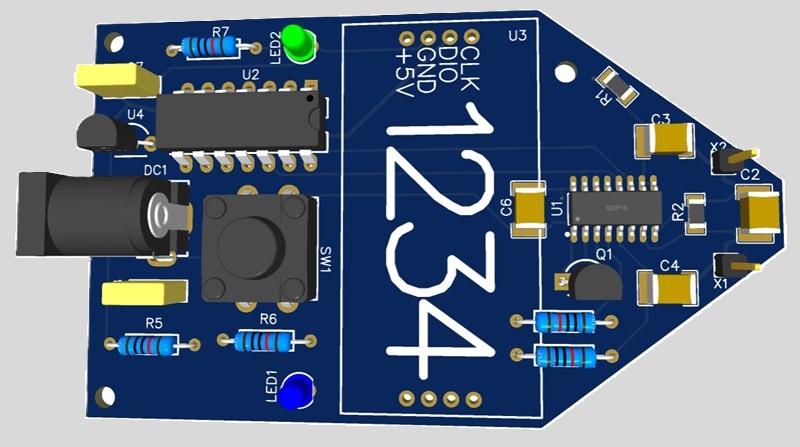
 Fig.1. Schematic diagram of the device |  Fig.2. Appearance of the device (in the case) for determining the charge on the capacitor C2 |
The U2 microcircuit is a microcontroller, whose task is to display data from U1 in the form of numbers on the U3 LED screen, received via the RA0-RA1 bus, and the polarity of the signal output to two LEDs LED1-LED2. In addition, U2 can change the sensitivity and reset the device by quickly or slowly pressing the SW1 button. If this button is held for less than a second, the point on the U3 display will move, along with the change in sensitivity of the device. If the button is held for more than a second, the device is reset (this procedure is similar to resetting electronic scales).
Element base
Below is a list of components required to assemble the device. You can use parts that are not listed in this list at your own discretion.
- U1 - 24-bit analog-to-digital converter HX711;
- U2 - 8-bit microcontroller PIC16F1824-I/P;
- U3 - 4-digit indicator TM1637, in the form of a ready-made LED module for Arduino;
- U4 - voltage converter to 5V L78L05 in TO-92 case;
- VT1 - p-n-p transistor S8550 in TO-92 case;
- DC1 - power connector for 12V DC005, 2.1-2.5 mm, Jack Female;
- SW1 - Push Button Switch Micro switch 12x12;
- LED1, LED2 - LEDs 3 mm, corresponding color;
- C1, C2, C6 - SMD capacitors, size 1812;
- R1, R2 - SMD resistors, size R1206.
The circuit of the device is designed so that with proper assembly and correct firmware of the microcontroller, its adjustment is not required.
Firmware file
The file for firmware of the microcontroller can be downloaded from here.
Instructions for firmware of the pic-controller can be obtained here.
Printed circuit board and case for 3D printing
Please note. In the schematic diagram, in the documentation for making the printed circuit board, additional capacitors C3 and C4 are indicated. They are only needed for additional experiments.
Production version: PCB (open)
The production option provides a set of documentation for manufacturing a printed circuit board in production:
GERBER file for PCB, BOM file of the specification of components and a schematic diagram showing the values of the elements.
All this allows you to immediately order a PCB, for example, here, and then quickly assemble it.
 |  |
Production version: 3D body (open)
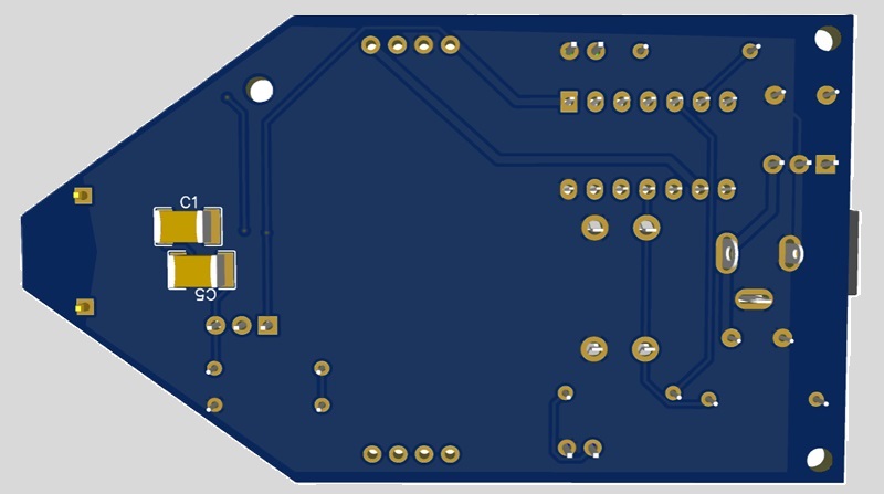
You can design the printed circuit board and case for 3D printing yourself. It is very important that capacitors C1, C3, C4 are located as close as possible to the U1 chip, and are accessible outside the case.
Experiment
To conduct the experiment you will need a laser pointer, preferably green, 532 nm, and with a power of up to 100 mW (for example).The color is chosen to minimize possible heating of the measuring capacitor.
The experiment itself is very simple. You need to turn on the device, reset it if necessary, and direct the laser beam to the measuring capacitor C2 (Fig. 2). Now you need to compare the device readings before and after illuminating this capacitor with a laser (Fig. 3). After illuminating, the device readings should increase by 15-20 times.
 Fig.3. Scheme of the experiment with a laser |  Fig. 4. Scheme of the experiment with a lamp |  Fig. 5. Modified circuit for an additional experiment |
The device will also react to illumination of C2 from a regular LED lamp, but, of course, the device readings will be much lower than with a laser (Fig. 4). It should be noted that in this case, the measuring capacitor can heat up to very insignificant temperatures. If we take into account the occurrence of the parametric effect and the potential difference obtained in this way, it will be orders of magnitude lower than the sensitivity of the device.
We will only note that the measuring capacitor is a completely closed electronic device that does not have galvanically connected contacts. But instead of the SMD capacitor C2, you can also install a classic lead-out capacitor, which usually has an additional protective coating. The effect will be slightly worse, but will also be very pronounced.
Additional experiment
You can record the polarity of the charge from different light sources. To do this, you need to solder two additional capacitors C3 and C4 into the device. Capacitor C2, however, needs to be unsoldered (Fig. 5). Now you need to alternately illuminate capacitors C3 and C4, and look not only at the display readings, but also at the color of the LED that lights up (LED1, LED2). If a red LED lights up when C3 is illuminated, then when C4 is illuminated with the same light, a blue LED will light up.
Note. The device (Fig. 1) can also detect powerful electrical impulses, lightning discharges, displacement currents, and, if the operator has certain skills, geopathogenic zones.
Conclusions
The appearance of a charge in the measuring capacitor when it is irradiated with light is somewhat reminiscent of the photoelectric effect [7], or more precisely, the photovoltaic effect [8]. However, in the first case, there must be a so-called "red border" of the photoelectric effect, which is not observed in this case. In the second case, a galvanic connection between the electrodes and the presence of semiconductor materials are necessary, which we also do not see here. The common property observed for all the listed effects is inertialessness. This property refutes the hypothesis about the possible appearance of a charge due to the heating of C2, since the effect appears immediately after the beam hits this capacitor, and not gradually, depending on its heating. In addition, the effect of the appearance of a charge on C2 also occurs with ordinary light from an LED lamp.
As was already noted at the beginning of the work, a longitudinal wave manifests itself through the induction of a charge in a substance. In this case, the higher the oscillation frequency, the more charges arise with the same amplitude. This experiment and the property of longitudinal waves allow us to conclude that light is not only transverse, but also longitudinal (scalar) waves, which cause a charge to appear in the capacitor C2. During the experiment, the induced charge accumulates in the dielectric of this measuring capacitor (on one of its plates), and a potential difference arises between the plates, which is immediately shown on the display of the device.
The author hopes that this experiment will open up new possibilities for physics, and will allow longitudinal waves and scalar energy to take their rightful place in electrodynamics.
Materials used
- Wikipedia. Photon.
- Tomilin A.K. Fundamentals of Generalized Electrodynamics. [PDF]
- Kuznetsov Yu.N. Detection of longitudinal light. [Webarchive]
- S.A. Abdulkerimov, Yu.M. Ermolaeva, B.N. Rodionov. Longitudinal electromagnetic waves (theory, experiments, application prospects), Moscow, 2003
- Koltsov S.V., inventor of the FSC. Medical conference. [Webarchive]
- Lomakova E.M. Pavlov A.N. (MTUCI) Ermolaev Yu.M. (Istok) Changes in the physical properties of Epiphany water when exposed to electromagnetic radiation. The world of science. 2013
- Wikipedia. Photoelectric effect.
- Wikipedia. Photovoltaic effect.